


a. STANDARD OPERATING CONDITION
IMEFY SpA transformers, unless otherwise agreed, are suitable to be installed in environments and places in accordance with standards IEC 60076-1 and IEC 60076-11, in any case the complete characteristics are shown in the test report and in the rating plate always attached to the transformer.
b. OPERATING TEMPERATURES AND PROTECTION SETTING FOR OVER TEMPERATURE
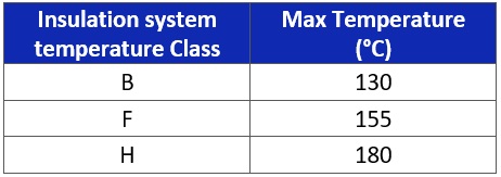
In the following table, depending on the transformer’s insulation system thermal class shown on its rating plate (Fig. 1 point 4) and on its test report, you can find temperature limits that the windings of the transformer can withstand while the machine is working:
Tab.1
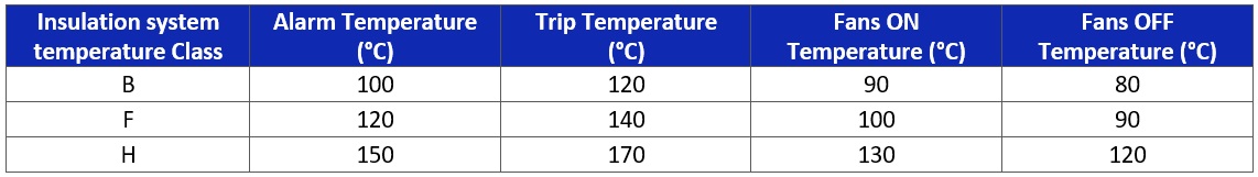
Here below a table with the suggested thresholds:
Tab.2
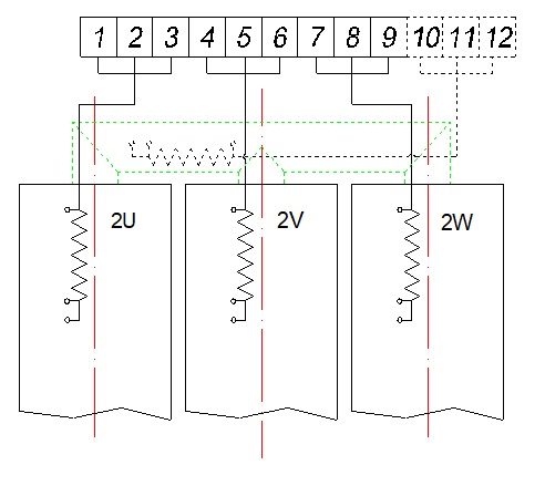
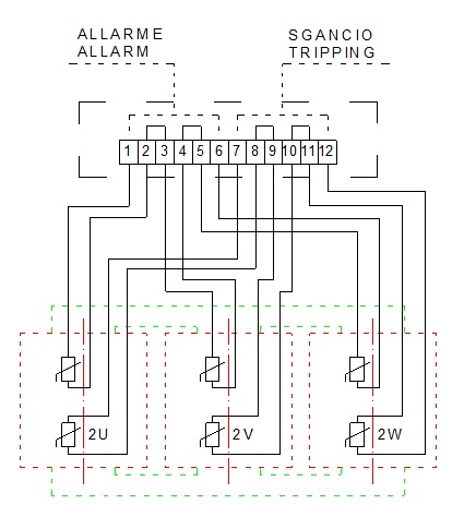
If thermistors have been requested instead of the thermosensors (PT100Ω), two of them will be installed for each LV winding, one will be used to signal the alarm and the other one to signal the trip (Fig. 7). In case there are fans on the transformer, an additional thermistor is required for each LV winding.
The thermistors shall be connected to a special control unit in order to manage the signals.
Fig. 7
c. NATURAL SUBSTATION DESIGN FOR TRANSFOMER HEAT DISPOSAL
For a correct installation and longer lifespan of the transformer, it is necessary to dispose of the heat generated by the magnetic core and the windings due to the joule effect, taking care not to exceed the temperature rise limits established in function of the thermal class of the transformer.
One must insure an adequate cooling by means of natural air circulation that must lap the sides of the transformer in a natural -down to up-motion.
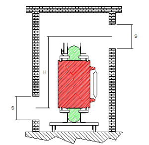
For this very reason it is imperative to place adequate openings in the room housing the transformer, in order to allow for every KW of heat shed, approximately 3,5 cubic meters of air must flow per minute.
In the installation room, apertures must be provided at floor level for the entry of cooling air and high on the opposite side, apertures must be provided for the exit of the heated air shed. (see picture)
The theoretical formula of the apertures in function of the KW to be disposed of, is the following:
S = 0,188 x P : √H . (see picture)
Where:
S = Surface in sqm. of entry aperture
P = Sum of the heat shed at no load and under load at 120°C in kw.
H = Height of the two apertures expressed in meters.
Fig. 8
d. INSULATING DISTANCES
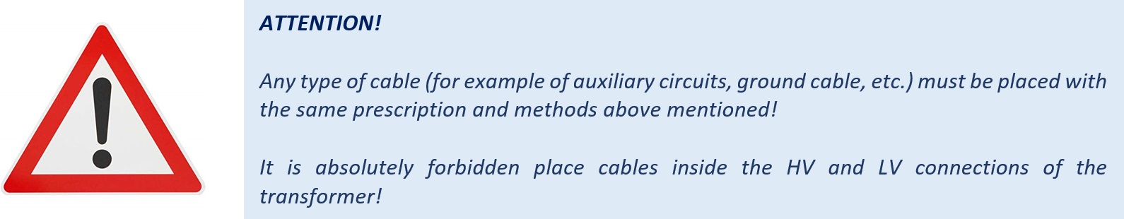
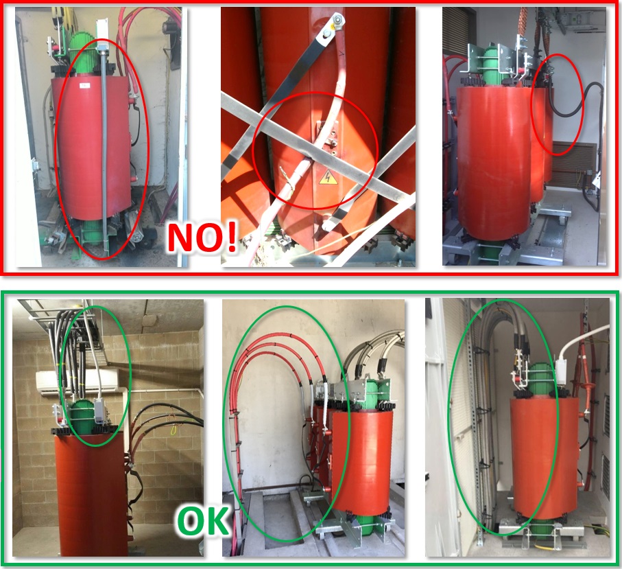
During transformer installation and operation minimum isolating distances between cables ( HV cables and HV cables shield , LV cables, Auxiliary cables, ground cables, metallic parts) and active parts of the transformers have to be peremptorily secured.
If the transformer is installed at an altitude higher than the maximum permitted standard, these distances must be increased by 1% every 100 meters exceeding 1.000 meters above sea level.
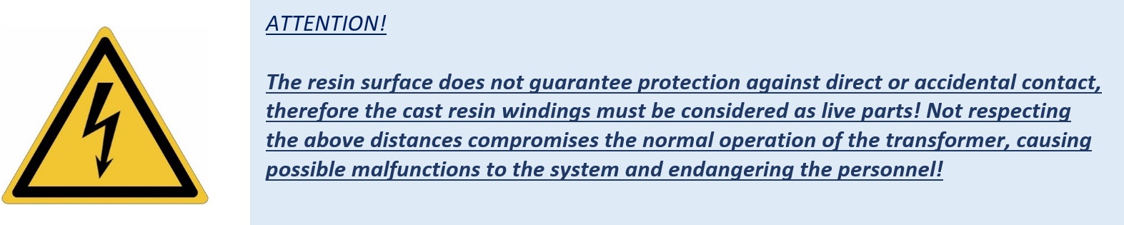
Fig. 9
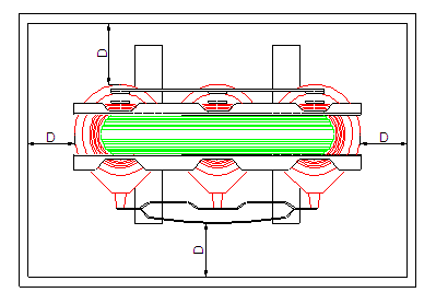
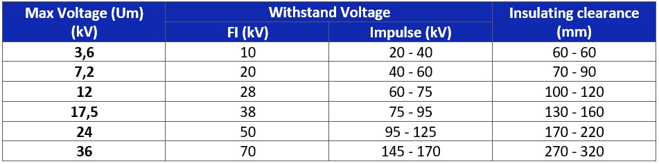
The minimum insulation distances (see "D" fig. 9) depend on the transformer insulation class and, more precisely, depend on the value of the lightning impulse withstand voltage "LI" (as shown in the standard IEC 60076-3: 2013 par.16.2).
Below the table with minimum distances we recommend:
Tab.3
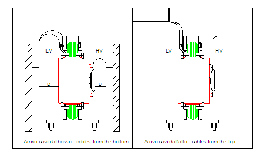
e. HV AND LV CONNECTIONS
The following drawing shows two options for LV and HV connections properly installed. In any case, the proper distances have to be insured in accordance with above point 3d.
Fig. 10
f. PARALLEL TRANSFORMERS CONNECTION
Here following some basic checks to be performed before connecting some transformers in parallel:
- Identical voltage ratio (and identical tap changer position)
- Identical operating frequency
- Identical Vector group
- Identical short circuit impedance (10% Tolerance)
It is also recommended, before carrying out the parallel operation, to check the concordance of the phases!
For any doubt or clarification do not hesitate to contact our technical department.
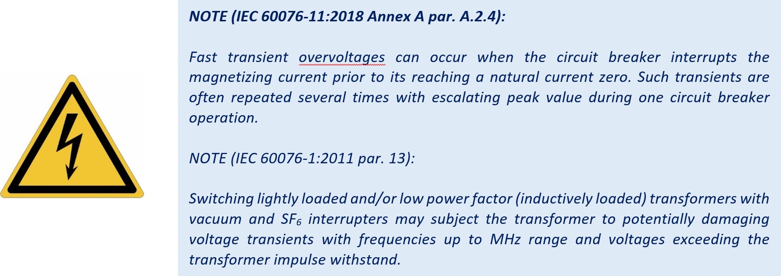
g. PROTECTIONS AGAINST OVERVOLTAGES
It is recommended to take the appropriate precautions in order to protect each transformer from possible overvoltages, which may be derived from the power supply, from performing maneuvers and/or from direct and/or indirect lightning strikes.
To carry out the correct sizing of the overvoltage protections, the value of the lightning impulse withstand voltage indicated in the transformer insulation class, shown in the test report and on the rating plate, must be taken as reference value.
h. IMPROPER USES
Here below the actions which can be considered as improper uses:
- Different movements from what is indicated
- Alterations of the parts of the transformer and / or its accessories
- Putting on the surface of the windings adhesive labels that are not part of the transformer
- Removal of information and warning signs
- Connections for which there is no provision made by the manufacturer
- Application of a higher voltage level than the one indicated on the rating plate
- Use the transformer with power higher than the one indicated on the rating plate
- Use of a supply frequency different from the one indicated on the rating plate
- Tightening of bolts and nuts with very different torque values compared to those indicated in Tab. 5 and 6
- Connection in parallel with unsuitable transformers
- Installation in unsuitable environments and with insufficient cooling air exchange
Any improper use of the transformer and/or any action not in accordance with what is prescribed in this manual shall involve the exclusion of any responsibility of IMEFY SpA and shall invalidate the warranty terms.